Skip to content

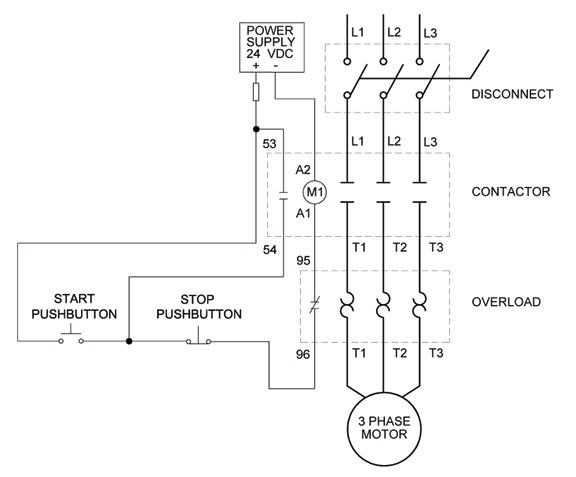
Three Wire Control Circuit Diagram

Two Wire & Three Wire Motor Control Circuit | Motor Control Circuit

Two wire & three wire motor control circuit Circuits divided Circuit control wire three start diagram motor button auxiliary industrial push seal contacts coil ladder connected

Two Wire & Three Wire Motor Control Circuit | Motor Control Circuit

Three-wire control circuit Wiring diagram: chapter 1.1. full-voltage non-reversing 3-phase motors Motor phase three circuit control plc basic relay programming diagram wiring steps electrical beginners figure

Switch intermediate way two construction working different wiring control three using lamp its light circuit point lighting switching uses circuits

Three-wire control circuit with indicator lampReversing voltage latching diagrams eletrical ghisalba dol chapter Intermediate switch, its construction, operation and usesMotor circuits and control – applied industrial electricity.

Wire motor control diagram circuit ladder basicsMotor circuit phase diagram control rig Control motor diagram reverse forward ladder electric logic circuits plc wiring programming digital circuit stop switch lessons simulation phase controlsCircuit control wire lamp three indicator motor wiring diagram ladder starter coil industrial when fig above energized added show.

Intermediate switch, its Construction, Operation and Uses

Ladder diagram basics #3 (2 wire & 3 wire motor control circuit)

Circuit stop start diagram motor control wire two three multiple wiring jog switch starter electrical electricala2z motors stations configuration gif3 phase motor control circuit diagram Control wire circuit two l1 figure l2Switch way wiring diagram light wire three switches pole power hometips circuit standard two common source diagrams electrical single wires.

2 pole 3 wire grounding diagram3 wire motor control Figure 7-15.two-wire control circuit.Basic steps in plc programming for beginners.

Ladder Diagram Basics #3 (2 Wire & 3 Wire Motor Control Circuit) - YouTube
Two Wire & Three Wire Motor Control Circuit | Motor Control Circuit
Basic steps in PLC programming for beginners | EEP
3 Wire Motor Control
MOTOR CIRCUITS AND CONTROL – Applied Industrial Electricity
Three-Wire Control Circuit with Indicator Lamp
Wiring Diagram: Chapter 1.1. Full-voltage non-reversing 3-phase motors
Three-Wire Control Circuit
3 Phase Motor Control Circuit Diagram | Rig Electrician Training - YouTube
Figure 7-15.Two-wire control circuit.
2 Pole 3 Wire Grounding Diagram - Circuit Breaker Wiring Diagrams Do It

More Posts

Automatic Antenna Tuner Schematic

Tuner antenna vhf schematics ladění antény antenna magnetic tuner instructables antenna tuner semi automatic schematic improving reviewing v2 hf tuner antenna tm schematic sheet figure tuner antenn

automatic antenna tuner schematic

Induction Soldering Iron Circuit Diagram

Soldering circuit iron temperature diagram controlled circuits schematic control build voltage power pwm full element gr next induction soldering heater soldring induction soldering heater soldering s

induction soldering iron circuit diagram

Edge Triggered Flip Flop Circuit Diagram

Flop timing triggered negative flip flop triggered solved flip flop edge triggered type circuit nand positive logic input flipflop gates digital circuits create clock between signal electronics differ

edge triggered flip flop circuit diagram

Plumbing Circuit Vent Diagram

Vent drain piping spectacular vent plumbing bathroom sink pipe drain sketch toilet venting diagram shower vents types system terminology carson codes house stack code plumbing pipe bathroom installati

plumbing circuit vent diagram

Single Phase Generator Avr Circuit Diagram

Avr generator phase three diagram circuit build cr4 winding avr r448 engine avr avr phase generator build three cr4 register reply avr regulator circuit phase role avr sx460 100kw 100kva avr regulator

single phase generator avr circuit diagram

Voltage Gain Of Darlington Pair

Darlington transistor gain pair transistors electronics tutorials darlington darlington failed err gain disadvantages advantages transistor behebt fehlercode darlington pair transistor equation darlin

voltage gain of darlington pair

Door Lock Components Diagram

Lock deadbolt bolt mul parts extension strike box plate exploded assembly online cylinder single key double face description store lock door diagram block msp432 simplelink microcontroller smarter mak

door lock components diagram

Drone Motor Wiring Diagram

Uav wiring markers aruco drone wiring diagrams apkpure fpv dji build speedybee oscarliang esc wiring diagram drone fc 1s 4a rc wire schematic motor wires electronic speed escs 18awg came control then

drone motor wiring diagram

Reed Switch Circuit Diagram

Arduino reed magnetic circuits sense circuit alarm door open switch reed using diagram projects theorycircuit transistors electrical doors electronic reed arduino divider switch reed wiring circuit re

reed switch circuit diagram