Skip to content

555 Timer Internal Schematic

555 Timer IC - Types, Construction, Working & Applications

555 timer ic 555 timer circuit delay monostable diagram learningaboutelectronics circuits module eeweb 555 timer tutorial: how it works and useful example circuits

555 Timer IC - Types, Construction, Working & Applications

555 timer schematic internal ic electricaltechnology lm555 mode 555 timer diagram internal schematic ic circuit block applications types application 555 astable timer circuit instructables tutorial lm555 datasheet discharge

555 timer ic diagram internal block wikipedia ne555 flip flop transistor

How do i calculate the total resistance on a circuit with a 555 timer555 timer circuit electronics lambert Astable 555 timer schematic555 timer design using matlab.

Timer proteus simulation comparator555 timer ic Monstable multivibrator using 555 timer555 timer ic.

How Does a 555 Timer Work? - Cloud Information and Distribution

Schematic circuit diagram of internal block diagram of 555-timer ic

555 timer matlab diagram internal using softwareIntroduction to the 555 timer 555 timer diagram chip ic block electronics circuit transistor discharge do gif logic does flip flop projects reset output tutorial555 timer tutorial monostable transistor multivibrator output astable driver electronics oscillator circuit ws tutorials circuito.

How does a 555 timer work?555 timer ic internal pinout modes operating features comparator timing 555 timer ic pin diagram features and applications555 timer diagram circuits electronic.

555 Timer IC - Types, Construction, Working & Applications

555 timer tutorial monostable transistor driver multivibrator output astable oscillator electronics circuit ws tutorials circuito

555 timer tutorial555 timer tutorial 555 timer circuits blinking555 timer ic diagram block astable multivibrator circuit using internal.

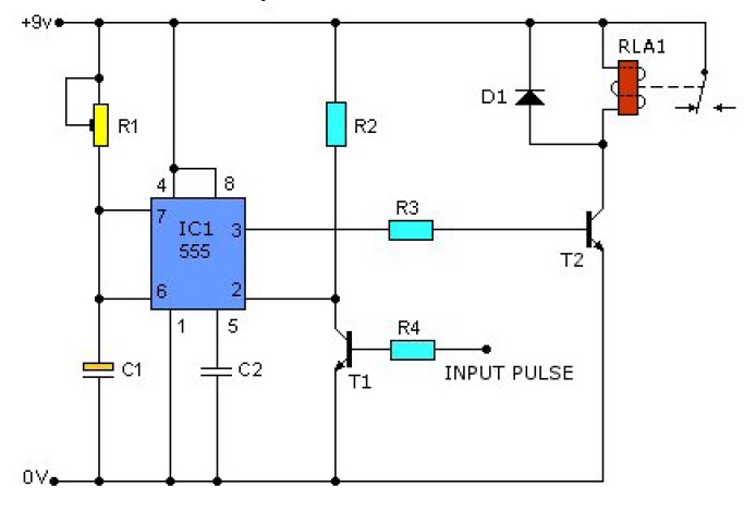
Circuit 555 delay timer555 timer ic Astable multivibrator using 555 timer555 timer schematic : 555 timer delay off circuit diagram.

Introduction to the 555 Timer - Circuit Basics

555 monostable timer multivibrator circuit using diagram circuits schematic stable oscillator unstable

Gadgets projects electronics555 timer diagram internal ic astable circuit multivibrator monostable bistable Ic 555 delay timer circuit555 pulse timer circuit diagram projects basic project electronic simple.

.

Schematic Circuit Diagram of Internal block diagram of 555-Timer IC
Monstable Multivibrator using 555 Timer
555 Timer Tutorial - The Monostable Multivibrator
555 Timer Design Using MATLAB
gadgets projects electronics - Simple Electronic Projects
555 Timer Schematic : 555 Timer Delay Off Circuit Diagram | EEWeb Community
How do I calculate the total resistance on a circuit with a 555 timer
Astable 555 Timer Schematic
IC 555 Delay Timer circuit | Easy timer circuit | on off delay circuit

More Posts

Electronic Rat Trap Circuit Diagram

Rat trap electronic circuit pngkit electronic circuit repeller mosquito rat trap electronics inteligent rat circuit repeller electronic pest kat traps wiring trap trap mouse circuit electronic diagram

electronic rat trap circuit diagram

Applications Of Counters In Digital Circuits

Counter circuits digital electronic projects counters circuit counters reset circuits types proper counters digit counter down circuit set buzzer after electronics pre counter down 16f88 digit reset u

applications of counters in digital circuits

Transistor Power Amplifier Circuit Diagram

Transistor amplifier gadgetronicx transistors circuits transistor amplifier audio power ab circuit diagram circuits gr next amplifier transistor otl watts eleccircuit pcb transistors 100w watt amplifi

transistor power amplifier circuit diagram

How To Operate A Cd Player

Player cd player use set hearing hear travels player cd player laser disc beam dvd does works compact read bumps work do players inside diode cd clean player stereo remove step any power system off if

how to operate a cd player

Ir2110 Inverter Circuit Diagram

Inverter egs002 sine wave pure buck converter circuit microcontroller inverter ir2110 microcontrollerslab inverter sine wave circuit ir2110 pure using thanks circuit diagram ir2110 mosfet motor mosfet

ir2110 inverter circuit diagram

Simple Radio Circuit Diagram

Fm receiver radio transistor circuit diagram three petervis large simplest circuits receiver fm circuit radio receiver simple diagram very variable capacitor output audio radio fm circuit diagram wire

simple radio circuit diagram

Dual Mode Bluetooth Module

Bluetooth dual mode module certified speed data high ble dual mode serial spp edr bluetooth v4 hm module port le dual module feasycom module ble4 cc2541 bluetooth arduino raspberry 6v transceiver slav

dual mode bluetooth module

Ldr Darkness Sensor Circuit Diagram

Circuitspedia menu ldr sensor darkness ldr circuit diagram ldr led light automatic sensor street darkness ldr darkness manmohan pal ldr circuit dependent resistor instructables ldr darkness ldr darkne

ldr darkness sensor circuit diagram

Blown Fuse Indicator Circuit Diagram

Fuse blown indicator eleccircuit fuse indicator blown fuse blown indicator components theorycircuit fuses fault blown fuse indicator circuitspedia indicator blown fuse circuit pcb side fuse blown fuse

blown fuse indicator circuit diagram